As we know that SPI has 4 wires to transmit and receive data between a mast and a slave. Please refer the wiki page, SPI Bus for the detail information first.
The information is not enough for us to write a SPI program to drive a master device to transmit/receive data to/from a slave device. I'm interested the below picture of the SPI Bus wiki page because it can help us for writing the program.
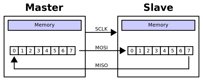
We can imagine that there is a ring composed of MOSI, MISO, and two shift registers. A basic communication program is to send a request and to wait for a response. For SPI, we send a request to a slave via MOSI and wait for a response from a slave via MISO.
Read-Id Command of Flash Part
The read-id command of the flash part, W25Q80DV is an example because I consider it is the simplest command for programming.
We want to write a program to get flash part id. The program transmit 9F to the flash part via MOSI and receive EF-40-14 from the flash part via MISO.
MOSI: 9F // Transmit Read ID command (9F) to get ID information
MISO: EF, 40, 14 // Receive ID information.
How do we write the program?
Transmit Data
Because SPI is a ring, when the master transmits a command with 1 byte (e.g., 9F) to the slave (flash part), the master also receives a dummy 1 byte from slave. The command is stored in TX FIFO and the dummy 1 byte is stored in RX FIFO. Therefore when the master transmits the command, it must clear dummy bytes in RX FIFO.
Receive Data
Please remember that SPI is a ring. If the master wants to receive data (e.g., id information with 3 bytes) from the slave (e.g., flash part), the master must send dummy data (e.g., 3 zero bytes) to push the slave to response data (e.g., EF-40-14.)
TX FIFO and RX FIFO
The master usually has 2 FIFOs. TX FIFO is to transmit data to the shift register and RX FIFO is to receive data from the shift register. I'll have another page SPI Host Controller and SPI Device Programming to describe the topic.
-Count
A blog of computer science that covers cryptography, UEFI BIOS, programming language, software applications, and network communication.
Sunday, March 22, 2015
Monday, October 13, 2014
The GUI of iOS 8
The iOS 8 has many things that we can learn when we design a GUI of an application. For example, the Cellular is defaulted to be turned off in Settings.
If we swipe it to turn on, the another setting, Enable 4G, appears.
We go back the Settings and find that the Cellular has > icon instead of "Off >".
If Cellular Data is turned off, the Enable 4G is hidden.
If we turn on Cellular Data, Enable 4G appears again and it is turned off. It seems that iOS 8 remembers the state of Enable 4G.
Then we turn off Cellular Data. The Enable 4G is hidden.
Finally we turn on Cellular Data and the Enable 4G displays as be turned on. It makes sense. iOS 8 remembers the state of Enable 4G and shows it only when Cellular Data is turned on.
I consider the GUI is very user-friendly. We can compare it with iOS 7 that Cellular Data and Enable 4G are independent. We are always confused when we turn on/off Cellular Data or Enable 4G in iOS 7, but iOS 8 eliminates our confusion.
-Count
The Cellular has > icon so that we know it has many sub settings. We swipe it to expand the sub settings. We know that the Cellular Data is the main switch of the Cellular feature.
If we swipe it to turn on, the another setting, Enable 4G, appears.
We go back the Settings and find that the Cellular has > icon instead of "Off >".
We enters Cellular again. We know that the Enable 4G depends on Cellular Data. It means that the Enable 4G can be turned on only if Cellular Data is turned on.
If Cellular Data is turned off, the Enable 4G is hidden.
If we turn on Cellular Data, Enable 4G appears again and it is turned off. It seems that iOS 8 remembers the state of Enable 4G.
We can proof the assumption by turning on Enable 4G.
Then we turn off Cellular Data. The Enable 4G is hidden.
Finally we turn on Cellular Data and the Enable 4G displays as be turned on. It makes sense. iOS 8 remembers the state of Enable 4G and shows it only when Cellular Data is turned on.
I consider the GUI is very user-friendly. We can compare it with iOS 7 that Cellular Data and Enable 4G are independent. We are always confused when we turn on/off Cellular Data or Enable 4G in iOS 7, but iOS 8 eliminates our confusion.
-Count
Circular Dependency
When I used the EDKII Package, I found that the package is similar to the UML package. We know that we should avoid the circular dependency in software design although the circular dependency always happens in natural domain.
Circular dependency is one of AntiPatterns but we cannot consider it as bad. What is benefit of it? When we want to public our source code of package that depends on a framework package (e.g., MdeModulePkg in EDKII.), if we don't want that our ideas in source code are easily stolen by competitors, we can modify the framework package to depend on our package to make circular dependency. Therefore the more circular dependencies we build, the more ideas we protect.
-Count
Circular dependency is one of AntiPatterns but we cannot consider it as bad. What is benefit of it? When we want to public our source code of package that depends on a framework package (e.g., MdeModulePkg in EDKII.), if we don't want that our ideas in source code are easily stolen by competitors, we can modify the framework package to depend on our package to make circular dependency. Therefore the more circular dependencies we build, the more ideas we protect.
-Count
Tuesday, October 7, 2014
Write Your Half BIOS
What is BIOS? BIOS is shorten from Basic Input Output System. Don't doubt it. That is really meaning of BIOS. Someone says that the purpose of BIOS is to boot OS. I don't think so. OS should be optional. What is Input? The keyboard and mouse are input devices. What is Output? The monitor and port 80 are output devices. If you write a program that enables input and output devices and your program is performed by CPU at reset vector, your program is BIOS.
I'm glad to see the page has the same idea of writing your BIOS. The page was written by Harrison Hsieh who is my former colleague.
http://biosengineer.blogspot.tw/2007/12/x86-bios4.html
My page just describes how to write a Half BIOS, a program that is performed by CPU at reset vector but it doesn't enable input and output devices. I also demonstrate how to run the Half BIOS with Bochs.
The following are source code of Half BIOS.
HalfBios.asm
Please follow the steps to build it by MASM and run it with Bochs.
Step 1. Build it with MASM611 or above.
> masm HalfBios.asm
The HalfBios.obj is generated.
Step 2. Update bochsrc.bxrc to change romimage file to HalfBios.bin
# romimage: file=../BIOS-bochs-latest
romimage: file=../HalfBios.bin
Step 3. Manually generate HalfBios.bin
> copy BIOS-bochs-latest HalfBios.bin
Please manually copy the 32 bytes with the signature "########" from HalfBios.obj to the offset 1FFE0h in HalfBios.bin. The content of 32 bytes is the program of Half BIOS.
Please make sure that there are EB F3 machine code at the offset 1FFF0h where is reset vector.
Step 4. Run Half BIOS with Bochs in debug mode.
C:\Program Files\Bochs-2.6.6\dlxlinux>..\bochsdbg.exe -f bochsrc.bxrc
-Count
I'm glad to see the page has the same idea of writing your BIOS. The page was written by Harrison Hsieh who is my former colleague.
http://biosengineer.blogspot.tw/2007/12/x86-bios4.html
My page just describes how to write a Half BIOS, a program that is performed by CPU at reset vector but it doesn't enable input and output devices. I also demonstrate how to run the Half BIOS with Bochs.
The following are source code of Half BIOS.
HalfBios.asm
Step 1. Build it with MASM611 or above.
> masm HalfBios.asm
The HalfBios.obj is generated.
Step 2. Update bochsrc.bxrc to change romimage file to HalfBios.bin
# romimage: file=../BIOS-bochs-latest
romimage: file=../HalfBios.bin
Step 3. Manually generate HalfBios.bin
> copy BIOS-bochs-latest HalfBios.bin
Please manually copy the 32 bytes with the signature "########" from HalfBios.obj to the offset 1FFE0h in HalfBios.bin. The content of 32 bytes is the program of Half BIOS.
Please make sure that there are EB F3 machine code at the offset 1FFF0h where is reset vector.
Step 4. Run Half BIOS with Bochs in debug mode.
C:\Program Files\Bochs-2.6.6\dlxlinux>..\bochsdbg.exe -f bochsrc.bxrc
We see that CPU performs the Half BIOS at the reset vector, f000:fff0, and then jump POST entry point.
-Count
Monday, October 6, 2014
Why I Like Bochs?
What is computer? I consider computer is a machine that quickly and automatically runs algorithm. The computer of Chinese text is 電 (electrical) 腦 (brain). Our brains are computers but not quick and correct. For example, I am an BIOS engineer. How do I proof it? I have blurred BIOS algorithm in my mind but it cannot be correctly run in my brain. I can tell you the algorithm but not the whole. I need to write BIOS program and run it in a machine to make sure that I know something in BIOS.
The machine, my brain, is not smart. I admire mathematicians who can present their theories in boards with very long formulas without computers. For me, a computer is necessary to help me thinking. I need burn BIOS in PC and see the process so that I can learn more.
But I don't want to use my PC to update BIOS. That has risk than using my brain. The idea is to use PC to emulate PC. I use a PC emulator to run a simple BIOS without breaking my PC at home. That is why I use Bochs, a PC emulator.
http://bochs.sourceforge.net/
-Count
The machine, my brain, is not smart. I admire mathematicians who can present their theories in boards with very long formulas without computers. For me, a computer is necessary to help me thinking. I need burn BIOS in PC and see the process so that I can learn more.
But I don't want to use my PC to update BIOS. That has risk than using my brain. The idea is to use PC to emulate PC. I use a PC emulator to run a simple BIOS without breaking my PC at home. That is why I use Bochs, a PC emulator.
http://bochs.sourceforge.net/
-Count
Sunday, October 5, 2014
Auto Run Debug Command with Script
The DOS debug.exe is a good utility to learn basic x68 Assembly language because we don't need to compile and link an ASM file and we just run it directly by entering commands. Sometimes we want to keep our interesting commands in a script file and automatically run it again with debug. How do we do it?
We can use a redirection (<) to read script file instead of the console. For example,
Please create script.txt that has the following lines:
a100
db 0a,0b,0c,0d,0e,0f
mov al,4
lea bx,[100]
xlat
(Enter to make a blank line)
t=106
t2
q
We can use a redirection (<) to read script file instead of the console. For example,
Please create script.txt that has the following lines:
a100
db 0a,0b,0c,0d,0e,0f
mov al,4
lea bx,[100]
xlat
(Enter to make a blank line)
t=106
t2
q
(please press Enter to make a blank line)
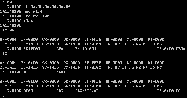
Please run the command.
debug < script.txt
Below is the result:
-Count
Thursday, October 2, 2014
Observe Reclaiming Process of EDKII Variable Services
This page provides a way to observe reclaiming process of EDKII Variable Services with UEFI Fault Tolerant Write Protocol.
EDKII Variable Services provides reclaim process with the recovery mechanism. When the platform restarts after power-off happens on NV reclaiming process, the driver checks the flag NV_FTW_WORKING that the NV reclaiming is not completed, it restores variables from NV_FTW_SPARE into NV_VARIABLE_STORE. Below files which are generated in build-time provide the regions information.
FlashMap.h
#define FLASH_REGION_NVSTORAGE_SUBREGION_NV_VARIABLE_STORE_OFFSET 0x590000
#define FLASH_REGION_NVSTORAGE_SUBREGION_NV_FTW_WORKING_OFFSET 0x5ae000
#define FLASH_REGION_NVSTORAGE_SUBREGION_NV_FTW_SPARE_OFFSET 0x5b0000
AutoGenFlashMap.h
#define _PCD_VALUE_PcdFlashNvStorageVariableBase 0xFFF90000U
#define _PCD_VALUE_PcdFlashNvStorageVariableSize 0x0001D000U
#define _PCD_VALUE_PcdFlashNvStorageFtwWorkingBase 0xFFFAE000U
#define _PCD_VALUE_PcdFlashNvStorageFtwWorkingSize 0x00002000U
#define _PCD_VALUE_PcdFlashNvStorageFtwSpareBase 0xFFFB0000U
#define _PCD_VALUE_PcdFlashNvStorageFtwSpareSize 0x00020000U
Please follow the steps to observe the reclaiming process.
Step 1. Burn BIOS in ROM and dump it with DediProg to observe the region of NV_FTW_WORKING.
We see the header of NV_FTW_WORKING. The header is used to check if data is successfully written by FTW protocol. If the writing data is completed, FTW driver set a flag in NV_FTW_WORKING to indicator the completion.
Step 2. Boot UEFI shell and observe NV_FTW_WORKING.
We use a tool to observe the region of NV_FTW_WORKING.
> ToolA.efi -read -id 3 -lba 1 -offset e000 -size 70
We see that the region only has header.
Step 3. Make variable reclaiming.
We use a tool to make reclaiming process happen.
> ToolB.efi -tc1:rt=1,size=1000
Step 4. Observe NV_FTW_WORKING and NV_FTW_SPARE
We use a tool to observe the region of NV_FTW_WORKING.
> ToolA.efi -read -id 3 -lba 1 -offset e000 -size 70
We a tool to observe the region of NV_FTW_SPARE.
> ToolA.efi -read -id 3 -lba 2 -offset 0000 -size 70
We find that the NV_FTW_SPARE is empty because FTW erased it after the large data were written successfully in NV variable store. If we disable the following code in FaultTolerantWrite.c,
#if 0
Status = FtwEraseSpareBlock (FtwDevice);
Ptr = SpareBuffer;
for (Index = 0; Index < FtwDevice->NumberOfSpareBlock; Index += 1) {
MyLength = FtwDevice->BlockSize;
Status = FtwDevice->FtwBackupFvb->Write (
FtwDevice->FtwBackupFvb,
FtwDevice->FtwSpareLba + Index,
0,
&MyLength,
Ptr
);
if (EFI_ERROR (Status)) {
FreePool (SpareBuffer);
DPRINTF_INST ("}..19\n");
return EFI_ABORTED;
}
Ptr += MyLength;
}
#endif
and repeat the step 1, 2, and 3 again, we can find that the the NV_FTW_SPARE stores the backup data.
> ToolA.efi -read -id 3 -lba 2 -offset 0000 -size 70
It proofs that the region of NV_FTW_SPARE is built by UEFI Fault Tolerant Write Protocol. The region is a backup of NV_VARIABLE_STORE that is reclaimed.
EDKII Variable Services provides reclaim process with the recovery mechanism. When the platform restarts after power-off happens on NV reclaiming process, the driver checks the flag NV_FTW_WORKING that the NV reclaiming is not completed, it restores variables from NV_FTW_SPARE into NV_VARIABLE_STORE. Below files which are generated in build-time provide the regions information.
FlashMap.h
#define FLASH_REGION_NVSTORAGE_SUBREGION_NV_VARIABLE_STORE_OFFSET 0x590000
#define FLASH_REGION_NVSTORAGE_SUBREGION_NV_FTW_WORKING_OFFSET 0x5ae000
#define FLASH_REGION_NVSTORAGE_SUBREGION_NV_FTW_SPARE_OFFSET 0x5b0000
AutoGenFlashMap.h
#define _PCD_VALUE_PcdFlashNvStorageVariableBase 0xFFF90000U
#define _PCD_VALUE_PcdFlashNvStorageVariableSize 0x0001D000U
#define _PCD_VALUE_PcdFlashNvStorageFtwWorkingBase 0xFFFAE000U
#define _PCD_VALUE_PcdFlashNvStorageFtwWorkingSize 0x00002000U
#define _PCD_VALUE_PcdFlashNvStorageFtwSpareBase 0xFFFB0000U
#define _PCD_VALUE_PcdFlashNvStorageFtwSpareSize 0x00020000U
Please follow the steps to observe the reclaiming process.
Step 1. Burn BIOS in ROM and dump it with DediProg to observe the region of NV_FTW_WORKING.
We see the header of NV_FTW_WORKING. The header is used to check if data is successfully written by FTW protocol. If the writing data is completed, FTW driver set a flag in NV_FTW_WORKING to indicator the completion.
Step 2. Boot UEFI shell and observe NV_FTW_WORKING.
We use a tool to observe the region of NV_FTW_WORKING.
> ToolA.efi -read -id 3 -lba 1 -offset e000 -size 70
We see that the region only has header.
Step 3. Make variable reclaiming.
We use a tool to make reclaiming process happen.
> ToolB.efi -tc1:rt=1,size=1000
Step 4. Observe NV_FTW_WORKING and NV_FTW_SPARE
We use a tool to observe the region of NV_FTW_WORKING.
> ToolA.efi -read -id 3 -lba 1 -offset e000 -size 70
We a tool to observe the region of NV_FTW_SPARE.
> ToolA.efi -read -id 3 -lba 2 -offset 0000 -size 70
We find that the NV_FTW_SPARE is empty because FTW erased it after the large data were written successfully in NV variable store. If we disable the following code in FaultTolerantWrite.c,
#if 0
Status = FtwEraseSpareBlock (FtwDevice);
Ptr = SpareBuffer;
for (Index = 0; Index < FtwDevice->NumberOfSpareBlock; Index += 1) {
MyLength = FtwDevice->BlockSize;
Status = FtwDevice->FtwBackupFvb->Write (
FtwDevice->FtwBackupFvb,
FtwDevice->FtwSpareLba + Index,
0,
&MyLength,
Ptr
);
if (EFI_ERROR (Status)) {
FreePool (SpareBuffer);
DPRINTF_INST ("}..19\n");
return EFI_ABORTED;
}
Ptr += MyLength;
}
#endif
and repeat the step 1, 2, and 3 again, we can find that the the NV_FTW_SPARE stores the backup data.
> ToolA.efi -read -id 3 -lba 2 -offset 0000 -size 70
It proofs that the region of NV_FTW_SPARE is built by UEFI Fault Tolerant Write Protocol. The region is a backup of NV_VARIABLE_STORE that is reclaimed.
Subscribe to:
Posts (Atom)